

991 GT3 Cup ABS - ESP Race Brake system for Porsche 911 by Albert Motorsport
- Albert Motorsport
- 1,206 Views

991 GT3 Cup ABS - ESP Race Brake system for Porsche 911 by Albert Motorsport
After the turning switches are installed in the front panel and tightened, the turning switches can be attached with the 12 position indicator disc. (Caution: Turning switches have plastic threads!)
Please check whether the switches can be turned easily and without much resistance. If not, please loosen the clamp screw and readjust the turning switch.
Advice: When tightening the turning switches with the clamping screw, they pull themselves against the front panel and some tension can be generated.
3.1 RaceABS/ESC
With the following components the ABS System can be enhanced into an ESC System from the beginning or on request even later in time.
ABS - ESP - Bremse für 991 GT3 Cup by Albert Motorsport
Manual for Race ABS/ESC- Porsche 991 GT3 Cup
1. Introduction
This installation manual describes how you can professionally install the ABS/ESC brake control
If there are any open questions about system installation or regarding technology/functionality of the brake control system, please let us know and we will support you on demand.
2. Safety Instructions
The Race ABS/ESP was developed by engineers and specialists and requires dedicated knowledge of automotive technology and experience in motor-sports/racing. Using the system is not without risks.
The buyer agrees to only use the system in the context of motor racing and not on public roads. We assume no liability for the reliability of the system on public roads. If the system is used on public roads, we assume no guarantee or liability for damage.
All system components are matched to each other and must not be exchanged for similar components. Otherwise, the system cannot be guaranteed to function properly and without restrictions.
Compliance with the given assembly specifications is necessary for error-free system function. This primarily includes installing the warning lamp (WL) LED so driver can see it at any time.
3. Package
3.0 RaceABS


4. Installation
To install the RaceABS system, please follow the sections below step by step and consider the written information.
All sections build on each other, making for a good guide to installation.
4.0 ABS Electro-Hydraulic Unit
The Electro-Hydraulic unit consists of HCU (Hydraulic Control Unit) and ECU (Electronic Control Unit). The ABS/ESC unit can be installed to the original mounting points in the vehicle without any issue.

The original brake pipes (A, B, C, D) from both master cylinders to the “brake pipe connector” (Bracket) must be removed. A,B,C,D are not required any longer.
Attention:
Before loosen the brake pipes (E, F, G, H) from the bracket, please mark the brake pipes according to the labelling on the bracket - for example FL (front left), FR (front right), RL (rear left) and RR (rear right). This will prevent the brake pipes from being mixed up later.
1. Below view is after having removed the original 991 Cup-bracket (“brake pipe connector”).

Bracket
2. Below view is after having removed the original 991 Cup-bracket (“brake pipe connector”).
Before installing the Electro-Hydraulic Race ABS unit into the vehicle, please mount the delivered brake pipe adapter (M14 x 1.5) to the hydraulic block and tighten them with a torque of 35 Nm.
PC = Primary Cylinder / master cylinder connection of the front axle SC = Secondary Cylinder / master cylinder connection of the rear axle
3. The Race ABS unit will be installed to the original 991 vehicle bracket including the delivered aluminium bracket.
The aluminium bracket is already fixed to the Race ABS unit by Knechtges Motorsport.
The aluminium bracket has 3 retaining pins.
Press the Race ABS unit/aluminium bracket with the 3 retaining pins deep into the original rubber damper elements until the aluminium bracket comes to stop and has contact to the rubber elements.
4. We recommend to continue to use the original brake pipes in the vehicle. However, it is required to slightly adjust and bend the available brake pipes so that they can be screwed easily into the hydraulic ABS unit without tension/damage.

Attention:
- Please make sure that there is enough space between the crossed brake lines so that they cannot touch each other even in hard racing driving events.
- When tightening the brake pipe, please always ensure that the brake pipe tube does not rotate with the screw nipple, otherwise the brake line may be damaged.
Hydraulic Connections:
A distance gap between the ABS/ESC unit and the brake pipes must be at least 10 mm.
(The reason is that when braking, the master cylinders moves slightly due to chassis fire wall elasticity and due to drivers pedal force activation. And because the ABS/ESP unit is mounted in rubber and it can therefore also move slightly while driving due to acceleration forces. We must prevent contact of ABS/ESP and brake pipes. This is achieved by the distance gap of 10mm.)


Install the brake pipes from master cylinder to ABS/ESC hydraulic unit.

Wiring Harness

Wiring Harness DIN A4 Attachment Page 4
The wiring harness is one of the most important components for electronic systems. Wiring harness should always be carefully installed in the vehicle.
At the points where the wiring harness is routed through body openings, please make sure that the rubber grommet already in the wiring harness or on the vehicle is used to avoid chassis metal contact/damage.
Attention:
- All plug connections are installed to the wiring harness after the cable harness has been completely routed in the vehicle!
- Vehicle fuses are only plugged into the fuse box after the system has been completely installed.
4.1.0 Cable Entry into Chassis Body
Remove the rear plastic panelling from the front left wheel housing.
To route the wiring harness into the interior, a hole must be drilled at the location shown in the picture below.

Drill a 28mm hole at the location shown - preferably with a stepped drill.


The rubber grommet on the wiring harness is only inserted into the hole after all the cables have been pulled through the 28mm hole up to the first branching point.
4.1.1 Cable Harness into Interior
After the rubber grommet is installed and the rest of the wiring harness is in the interior, it can be routed as shown in the next figure.
The ABS wiring harness is routed behind the display -along the original vehicle wiring harness- to the center console. That's where the main branch point is.


4.1.2 Power Supply and Fuse Box
The main power supply is routed from the main power switch to the fuse box as shown in the picture.


To attach the fuse box, please drill two holes in the (aluminium/magnesium) dashboard bracket- support.

Please insert screw rivets into the dashboard support or drill the appropriate thread for the fuse box fastening screws.

Please make sure that the fuse box is fixed reliably and safely.
The fuse box must not be fastened with DUAL Lock, Velcro, double sided adhesive tape or similar.


The 3 cables for 12V power supply will be connected to the fuse box:
Attention:
When connecting the 12V power supply cable to the fuse box, please make sure that the 12V power supply cables are connected to the fuse box with a small bend/radius.
This is important so that the cable is strain-relieved and cannot become loose during operation due to vibrations.
4.1.3 Connection of Wheel Speed Sensors


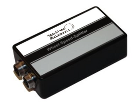
4.1.4 Connection of Wheel Speed Splitter
The Wheel-Speed Splitter is positioned on the left side behind the center console using Dual Lock.

4.1.5 Location of Warning Lamp/Fault Lamp (LED)
The Warning Lamp (LED) must be installed so that driver can see it at any time during driving/racing!
Please see a proposal for positioning for Porsche 991 Cup vehicles: In the middle of dashboard & just above the display.

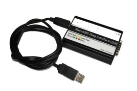
4.1.6 Location of Diagnostic Interface
It is best to attach the 9-pin diagnostic connector to the passenger side.
It is possible to attach the diagnosis interface in the vehicle or only plug it in when using the diagnosis.
4.1.7 Connection of Yaw Rate Sensor and Steering Angle Sensor
The pin layout for the yaw rate sensor and the steering angle sensor can be found on page 3 of the appendix.
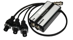
4.2 Parameter Box with Position Switch
With the parameter box it is possible to adjust the ABS/ESP detection thresholds on demand. For example: ABS control to be more or less sensitive.
Two (only for ABS) or three (for ABS/ESP) 10mm holes are drilled at a suitable point in the front panel.

After the turning switches are installed in the front panel and tightened, the turning switches can be attached with the 12 position indicator disc.
(Caution: Turning switches have plastic threads!)
Please check whether the switches can be turned easily and without much resistance. If not, please loosen the clamp screw and readjust the turning switch.
Advice: When tightening the turning switches with the clamping screw, they pull themselves against the front panel and some tension can be generated.

The parameter box will be fixed behind the front panel of the center console opposite to the wheel speed splitter.
The box will be fixed with Dual Lock and connected to the wiring harness of the 4-pin round connector.
4.3 Yaw Rate Sensor
The yaw rate sensor is a safety part. For a safe ESC function, this must be fixed (mechanically screwed) to the vehicle chassis tunnel with the supplied damping rubber blocks.
It is not allowed to fix it with double-sided tape or Velcro.
Please keep the yaw rate sensor as straight as possible to the longitudinal axis of the vehicle with the connector pointing towards the front of the vehicle.
Mark the sensor mounting points on the chassis body (blue marked dots on the picture below).

To get the rubber elements be installed, drill a 3mm hole in the 4mm thick aluminum vehicle chassis center tunnel and drill/cut an M4 thread into it.

After threaded holes have been made, the sensor can be screwed onto the rubber blocks.

4.4 Steering Angle Sensor
The inner, rotatable part of the steering angle sensor is attached to the steering column with 2- component adhesive.
For better adhesion of the 2-component adhesive on the smooth steering column, sand and roughen the full extent of the adhesive area with fine sandpaper (e.g. 600 grit).

The large white plastic wheel of the original steering angle sensor must be reduced in its thickness distance.
Reduce thickness of the white plastic material so that the grub screw still can be used.
But take away as much material as possible to reduce thickness of the white plastic wheel.
This procedure needs to be done otherwise the steering wheel hub will press against the steering angle sensor
via the white plastic wheel and jams it and generate unacceptable tension to the new ESC steering angle sensor.
The bracket supplied must be positioned in the available nose below the steering column and tightened with the metal-clamp.
The ESC steering angle sensor (black) must have it’s position with the (black) nose between the two pins as shown on the picture.

The calibration of the ESC steering angle sensor is described in the following chapter
5. "Get the System Up and Running".
5. Get the System Up and Running 5.0 Brake System Bleeding
As in standard vehicles, the brake system including Race-ABS/ESC can be bleeded quite normally
with any type of bleeding device or by pumping/activating the master cylinder mechanically by foot.
Attention: During the first start-up (not the first test drive) and right after the brake system
bleeding is finished first time the brake pedal should be activated 2-3 times to build up brake
pressure on all 4 brakes. After that then bleeding should be repeated a second time again.
5.1 Diagnostic by using the Laptop
With the diagnostic tool, the system can be calibrated and checked for errors before use. This should
be done before each race weekend.
Read fault memory. The fault memory only shows numbers. These can be translated via the FSP Bibl.
Note: If there is no error in the system, the error memory shows the value 255.
In the next figure, for example, error 2 is entered. This fault was entered by unplugging the rear right
sensor from the wiring harness.
The numerical values can be translated into text using the FSP Lib (fault memory library) button.
After the sensor is reconnected to the wiring harness, the error is still stored even after an ignition change.
Only after pressing the Clear FSP (delete the error memory) button is it deleted.

After installation, the wheel speeds must be displayed correctly.
To do this, turn all the wheels one after the other and check
whether the wheel you just turned also shows a speed in the
diagnostic program.

Check all turning switches of the parameter box for correct display values.
To do this, compare all switch positions from position 1 to position 12 in the diagnostic program.
If other values can be seen, loosen the turning switch knobs and adjust to the correct number

The steering angle sensor must always be calibrated after a chassis adjustment (track adjustment).
To do this, the LWS CAL1 button must be pressed on page 2 of the program in order to put the sensor into calibration mode.
This then assumes status 5 and a maximum steering angle of 3276,7.

After that: LWS CAL2 to bring the sensor to the zero position.

After successful calibration, the error memory must be deleted!
5.3 Parameter Select Switch and recommended basic setting for Porsche 991 GT3 Cup
The settings listed here are guidelines.
Driver perception and vehicle set-up have a major impact on these settings.
- Porsche
- 991
- 911
- Albert Motorsport
- Porsche 911
- upgrade
- system
- ABS
- 991.1
- 991.2
- ABS System
- ABS ESP
- ABS ESC
- Porsche 991
- Porsche 991 ABS
- update